
The Märklin Diary of a 44 yr old Kid
|
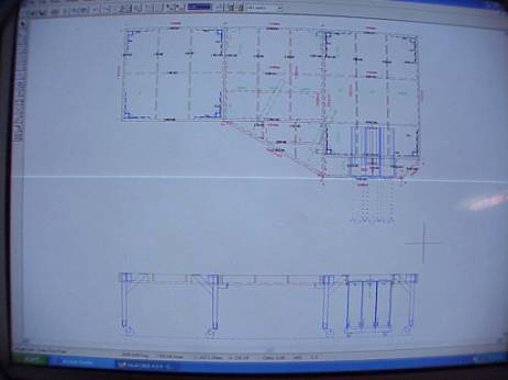
The purpose of this layout would be to have a diverse spectrum of rolling stock coming across the various areas. Secondly it would allow the operator to service the various locos in the BW as well as perform shunting operations in the BW area. Occasionally the mainline will be crossed to service the factory in the upper right hand corner as well as the freight building in the upper left area. The lower hidden siding allows for the parking of special excursion trains as well as loading of new train assemblies (left lower dead end track) from the Trainsafe display tube system. Lastly the system has to be able to be dismantled into 3 sections facilitating removal down the stairs and through doors. Ideally the shadow and mainline operation should be fully automatic with manual override. I intend to make this layout the cornerstone of my bonusroom/office area, hence the name Eckstein. |
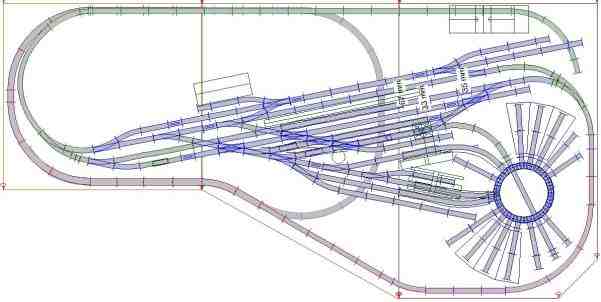
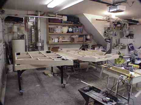
Eckstein upper level, consisting of Bonn station, Faller 981 factory and extensive BW. Entire upper level is K track. The long riser in front leading up top the station will be the Paradestrecke. |
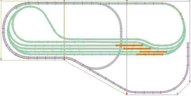
Eckstein upper hidden siding (located 10cm below station level) Entire upper hidden siding is K track. |
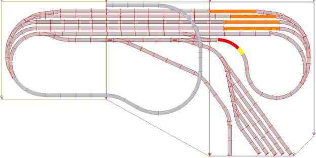
Eckstein lower hidden siding. Entirely C track. Lower hidden siding is 28cm below upper level to provide ample clearance for staging tracks. Left dead end track provides connection to Trainsafe display tube system. I intend to make the staging area (and the fifth parallel track connecting to staging area) to be able to isolate from the rest of the layout so I can load trains with the 6021 Marklin control. Remainder of system controlled by Intellibox, and future computer control. |
|
|
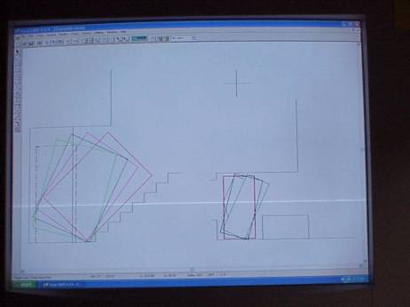
| First a drawing to determine maximum size to fit downstairs and through the door! | Then a drawing for the base construction |
 |
 |
 |
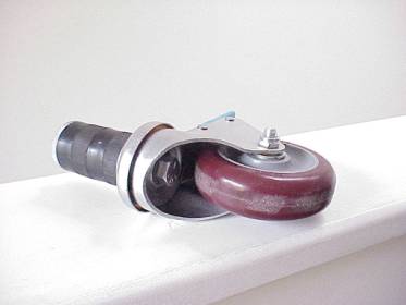
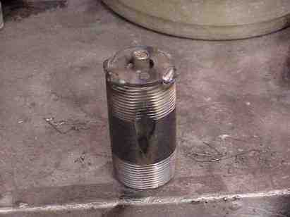
| The castors are of the "expanding sleeve" type and fit quite nicely into a 1 1/2" pipe nipple which in turn gets welded into the square tubing. | Prior to welding the pipe nipples into the tubing they got modified by welding a stop bolt assembly onto the base of the nipple with the idea of providing a "stop" as to the depth to which the expanding sleeve castor can be inserted. |
 |
 |
| Slightly modified 1 1/2" pipe nipple. | Above picture shows the head of the stop bolt. This will give a height adjustment of approx. 12mm maximum per leg should uneven floors be encountered. |
 |
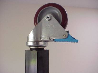 |
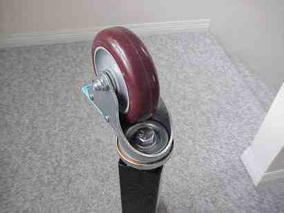
| The castor gets inserted and the bolt tightened providing a solid castor to leg connection. | Above picture of castor in 6mm extended position. |
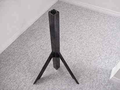
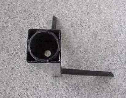
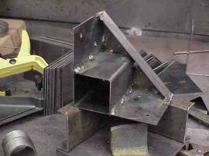
| To mount these legs onto the frame and yet make them easily removable required making up some "pockets" which were incorporated in the corner brace assembly. The idea behind this was that the table section can be lowered onto the legs by two people whilst a third person inserts the legs into the "pockets" and the weight can be put onto them without having to bolt them. |
 |
 |
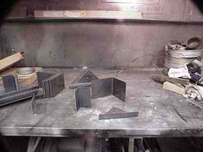
| Leg pocket /corner brace components prior to assembly. | Fabricate the corner braces with leg sockets |
 |
 |
| Assembly of leg with lateral bracing. | Completed cornerbraces/legsockets |
 |
 |
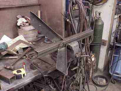
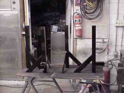
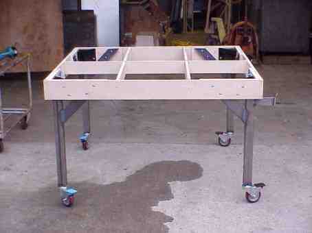
| Completed leg assemblies (note lateral support on right and front legs). Once the table section is resting on the legs, the leg brace bolts get inserted and tightened giving a solid connection impervious to lateral movement. |
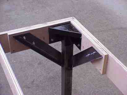
Installed leg assembly mounted in socket |
| Once the table section is resting on the legs, the leg brace bolts get inserted and tightened giving a solid connection impervious to lateral movement. |
 |
 |
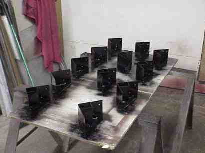
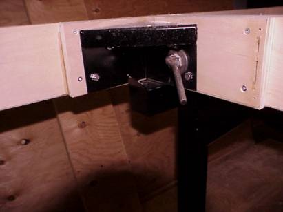
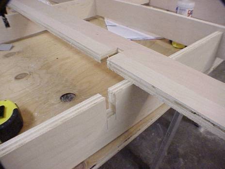
| Module connector bolt. | The legs facing the center module have a lateral support with stop welded onto them; reason for this is to provide support for the center module during disassembly once the 3/4" module connector bolts are removed. |
 |
 |
|
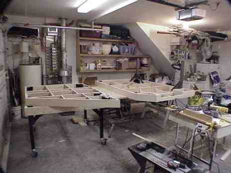
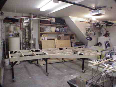
Left module is on its feet!! Support (for center module disassembly) on right side, center module is bolted to left and right module Then it's just a matter of rolling the two outside modules outward until they hit the stops, lifting out the center module, remove the legs on both outside modules, and voila!, you have a transportable layout!! |
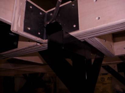
Detail of inner frame construction |
Building the right module (upside down on right) left and center module on left. |
Right module, installation of legs. |
Working on the last module on right. |
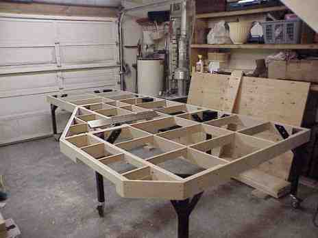
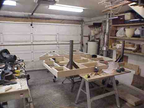
Endview of all 3 modules assembled. |
 |
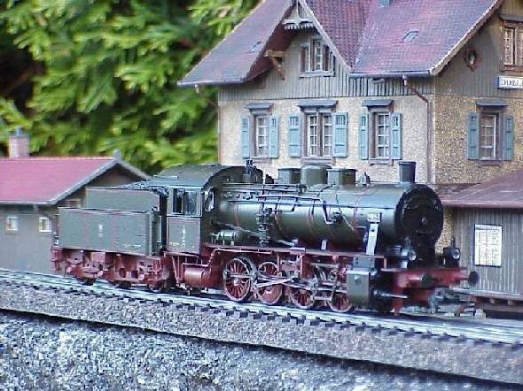 My favorite lok. |
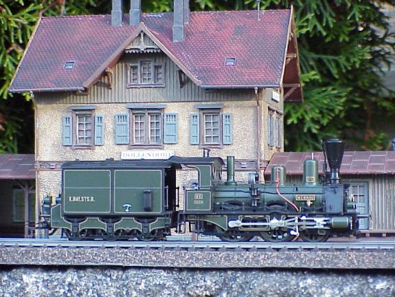 A model of the Guglingen Station renamed Dollendorf. |
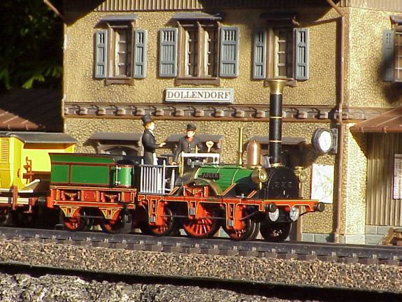 The Adler is one of a very photogenic little locomotives! |
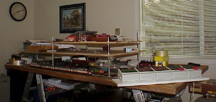 A temporary layout where such things as height between tracks, braking sections etc were checked. And of course also a handy location to try out "new aquisitions"!! |
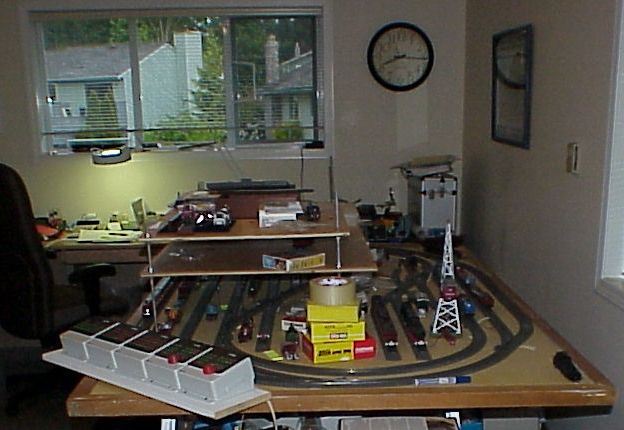 The corner by the clock is the corner into which my layout will go, as per following picture showing the room layout with my home office on the left. |
 |
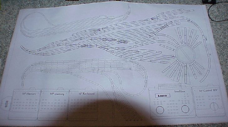 Heres a picture of the switchboard Im planning to make, plotted full scale to check functionality. |
Images are Copyright 2003, John Monsieurs
John can be reached at: John Monsieurs
Home - Märklin